Power Network Class
This page explains the variables and functions used in the power network class (power_network), as well as one detailed example to better understand those variables and functions in an actual power system model.
Contents:
Power Network Class
This is one of the five main classes in GUILDA. From this class (power_network), all the power system models are derived.
Variables
-
x_equilibrium:Array containing the internal state of a generator. The internal state of each generator is composed of seven variables: 1. Rotor Declination Angle \(\small (\delta)\), 2. Angular Frequency Deviation \(\small (\Delta \omega)\), 3. Internal Voltage \(\small (E)\), 4. Automatic Voltage Regulator (AVR) Variable, and 5-7. Power System Stabilizer (PSS) Variables. -
V_equilibrium:Array containing the Equilibrium Voltage \(\small (V)\) ([real part; imaginary part]) for each busbar. -
I_equilibrium:Array containing the Equilibrium Current \(\small (I)\) ([real part; imaginary part]) for each busbar. -
a_bus:Array containing all the busbar information. The information on the i-th busbar is stored in the i-th element and can be obtained in the form of a structure likepower_network.a_bus{5}.V_equilibriumto get the equilibrium point of the voltage on the 5-th bus bar. -
a_controller_global:Array containing the Global Controller information. -
a_controller_local:Array containing the Local Controller information. -
a_branch:Array containing the branches infromation.
Functions
Simulate (simulate)
Function to simulate the system and output the results.
Class Structure: out = simulate(obj, t, varargin)
Input Arguments
t = [start, end]: Time \(\small (t)\).u: Input signal to the bus \(\small (u)\). \(\star\)idx_u: Target bus for the input signal. \(\star\)-
options: Struture-type variable that contains the information of the simulation conditions, such as-
linear:Sets if the simulation is linear (i.e.,true) or nonlinear (i.e.,false). -
fault:Sets the ground fault conditions in the form of{[start time, end time], target busbar}. -
x0_sys:Sets the initial value conditions of the state as a cell array per bus or as a vector with all buses stacked. -
V0:Sets the initial busbar voltage as a cell array per bus or as a vector with all buses stacked. -
I0:Sets the initial busbar current as a cell array per bus or as a vector with all buses stacked. -
X0_con_local:Sets the initial busbar local controller value as a cell array per bus or as a vector with all buses stacked. -
x0_con_global:Sets the initial busbar global controller value as a cell array per bus or as a vector with all buses stacked. -
rest_time:Forced termination time for the ODE15S Solver. -
do_retry: Sets if, once the forced termination time is reached, retry (i.e.,true) or not (i.e.,false) the numerical integration.
-
\(\star\) The input signal (u) and it's target bus (idx_u) are optional arguments. When used, they must be entered immediately after the time (t) argument.
Output Parameters (out)
Structure containing time response data of the system, composed of the following parameters
-
t:Time \(\small (t)\) as an array containing the "number of samplings". -
X:Response data of the state of the generators connected to each busbar as an array with "number of samplings" ✕ "number of device states". -
V:Busbar voltage as an array with "number of samplings" ✕ 2 (Real Part, Imaginary Part). -
I:Busbar current as an array with "number of samplings" ✕ 2 (Real Part, Imaginary Part). -
fault_bus:For each segment of the analysis, this field stores the cell array classification of the index of the busbar where the ground fault occurs. \(\star \star\) -
U_global:Contains the response of the input value from the global controller as an array "Input Ports of the Generator" ✕ "Number of Generators". -
U:Contains the response of the input value from the local controller as an array "Input Ports of the Generator" ✕ "Number of Generators". -
sols:For each segment of the analysis: This field stores in an array the solvers running in each segment. \(\star \star\)
\(\star \star\) For more information on what "for each segment of the analysis" means, as well as more information on the simulate class, plese refer to the dedicated section Simulating.
Add Local Controller (add_controller_local)
Function to add a local controller to the system.
Class Structure: add_controller_local(obj, controller)
Input Arguments
controller: An already defined controller (i.e., instance of the controller class). Note that, if a controller has already been added to the specified busbar, delete the previous one before adding.
Output Parameters
- None
Add Global Controller (add_controller_global)
Function to add a global controller to the system.
Class Structure: add_controller_global(obj, controller)
Input Arguments
controller: An already defined controller (i.e., instance of the controller class). Note that, if a controller has already been added to the specified busbar, delete the previous one before adding.
Output Parameters
- None
Remove Local Controller (remove_controller_local)
Function to delete a local controller from the system.
Class Structure: remove_controller_local(obj, idx)
Input Arguments
idx: Busbar with the controller to be removed.
Output Parameters
- None
Remove Global Controller (remove_controller_global)
Function to delete a global controller from the system.
Class Structure: remove_controller_global(obj, idx)
Input Arguments
idx: Busbar with the controller to be removed.
Output Parameters
- None
Note: For more information on the controller class related functions, please refer to the dedicated section Controllers.
3-Bus Sample Model
The 3-bus system model is the one used in the Guided Example, which is also covered in the reference text. For a detailed explanation, please refer to the mentioned materials.
The model is composed of
- 3 busbars.
- 2 generators (busbar 1 and busbar 2).
- 1 load (busbar 3).

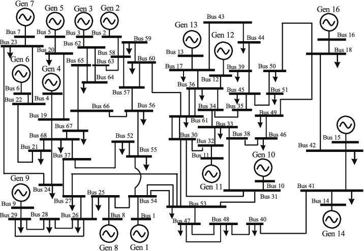
IEEE 68-Bus Model
The IEEE 68-Bus 16-Machine System Model is already implemented in GUILDA derived from the power_network class. For more information on it refer to the book Robust Control in Power Systems.
In this model, the Synchronous Generator is modelled by the 1-Axis model (i.e., generator_1axis class) and the Loads are modelled by Constant Impedance Model (i.e., load_impedance class).
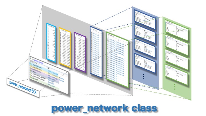
Power Network Class - Properties
In GUILDA, the power system model is defined as a variable of the class power_network. The purpose of this section is to provide an imagine of what kind of power system model is implemented by looking at the values of the properties of this power_network class (Click on the Illustration ↓).